Abstract: This article introduces the maintenance and upgrading project of the Gansu North Santai Chemical Co., Ltd. power integrated protection system, adopts intelligent power meters, and collects various electrical parameters and switch signals at the distribution site. The system adopts on-site local networking method. After networking, it communicates via the field bus and transmits it to the background. The Acrel-2000 power monitoring system realizes the real-time monitoring and management of power distribution loops in the distribution room.
Keywords: Gansu North Santai Chemical Co., Ltd.; chemical industry; smart power meter; Acrel-2000; power monitoring system;
0 Overview
Gansu North Santai Chemical Co., Ltd. is located in Baiyin District, Baiyin City. There is a substation on the site, the substation is located on the third floor of the substation, and the second floor is the cable bridge room.
There are 14 35kV high voltage distribution cabinets, 20 10kV distribution cabinets and 44 0.4kV low voltage distribution cabinets on site. The original 35kV and 10kV high-voltage part of the existing computer comprehensive protection system, but this system in the course of operation, there are miscellaneous security, measurement is not allowed, the process is not clear and various issues such as the use of electricity, combined with GB 17167 on the configuration of electrical energy metering requirements At the same time, in order to facilitate the smooth development of the company’s unit cost assessment, it is planned to routinely maintain the protection, measurement, metering, and communication systems of the high- and low-pressure integrated protection equipment, and upgrade the measurement system of the low-pressure comprehensive protection equipment. The low-voltage outlet circuit adds multi-function power meters and integrates the data of the original high-voltage system on a set of back-end software to realize power monitoring and energy metering for each process.
In order to realize intelligentization and modernization of power supply and power distribution at the customer end of the plant, a background monitoring system with simple operation, functional and practical performance, and stable and reliable performance is needed for the project to remotely and real-timely use electricity in the plant area. Monitor and realize the remote monitoring of electricity in each process within the factory, so that the management personnel can accurately grasp the power consumption of each process.
The 35kV and 10kV power distribution cabinets have been connected to a monitoring system. It is necessary to add monitoring and control devices on the outgoing side of the 0.4kV low-voltage cabinet and connect to the back-end system for remote monitoring. There are 44 low-voltage cabinets on the site, of which 34 outlet cabinets, Since the two low-voltage incoming lines and the emergency power supply incoming line have been incorporated into the high-voltage cabinet back-stage monitoring system, only a multi-function meter is added to the outlet circuit of the 34 low-voltage outlet cabinets. There are a total of 236 statistical outlet circuits, some of which are The outlet circuit is a backup circuit, and there is no wiring on the outlet side. There is a part of the circuit behind the device has been disabled, there will be no more power, and finally a total of 191 outlet circuits need to be monitored. In order to monitor the power supply in the plant area, it is necessary to integrate the high and low voltage measurement and control devices.
As all the loops have to be retrofitted, multimeters need to be added and more open-ended current transformers are used for retrofitting, and construction costs are higher. Customers are now requesting the same process according to the different processes in the plant area. The electric equipment is placed close together for monitoring, that is, a multi-function instrument monitors multiple electric devices in the same process. Since the electricity monitoring at the site only needs to separately monitor the power consumption of each process, the measurement method is the same. It is feasible to reduce the amount of instrument and open transformers and construction costs, but it is impossible to check the specific power consumption of each device when monitoring and searching. The mainframe of the system is placed in the 10kV duty room on the third floor, and the original high-pressure integrated protection system is integrated. Finally, the remote monitoring of all processes using the monitoring system of our company is realized.
1 Demand analysis
To ensure the statistics and analysis of the electricity load of Gansu North Santai Chemical Co., Ltd. and the real-time monitoring of hazard sources. The real-time on-line monitoring of the voltage, current, and power parameters of the 35KV high-voltage comprehensive protection project, the 10KV high-voltage comprehensive protection system, and the low-voltage power line of the low-voltage inlet-outlet circuit shall be performed on the project site. Once the monitoring point is monitored for abnormal parameters, the alarm can be detected in time and the relevant personnel take necessary measures to avoid safety accidents. The automatic meter reading function of sub-process saves manpower and material resources. The function of power trend curve can intuitively display the working status and time of each loop. It is convenient for users to find out the abnormal power consumption circuit and carry out timely rectification, establishing a multi-level energy metering system to provide energy. Analysis basis.
This technical condition applies to the power monitoring of the 35KV to 10KV to 0.4KV power distribution room in Gansu North Santai Chemical Co., Ltd. plant. The supplier's products should have high safety and reliability, be easy to expand, and be easy to maintain and maintain. The product provided by the supplier shall meet at least the technical conditions, but it is not limited to this. The technical performance of the supplier shall meet the requirements for data monitoring of the power distribution room.
data collection
It automatically collects the analog data of all the electricity meters at the site and automatically collects the on-off status such as on-site switch status and fault status.
Supports real-time acquisition, automatic cycle acquisition (timing acquisition), configurable period (1 minute to 24 hours).
Support data transmission correctness test, abnormal data processing automatically.
Support multi-thread processing mechanism, improve data collection efficiency, and data acquisition for multiple devices at the same time.
The real-time display of data is based on a visual display mode of the power distribution cabinet. The switch disconnection and fault status of each circuit are visible.
Data analysis and processing
Comprehensive statistics and analysis of data need to achieve the following functions:
The statistics and calculations for hours, days, months, and years of electricity data for each device.
Calculate the power consumption (active and reactive power) of each outlet circuit and sub-processes.
Data query and display
Requirements can facilitate the implementation of client inquiries and inquiries at all levels of management personnel, query interface can adapt to the requirements of all levels of management personnel can support flexible conditional combination of query and comparative analysis, various types of statistical analysis of data can be used flexibly using reports and other charts Intuitive display function.
The data display function is divided into operation level and management level according to different users' different rights.
authority management
Requirements for different users to give different roles, can be authorized to function submenu, specific file records, data records.
The system requires a reasonably complete user security control mechanism, which can effectively protect the information resources in the application environment and prevent the loss, theft and destruction of information.
error alarm
Fault judgment and alarm have automatic fault judgment and use sound and light alarm function. Types of alarms include microcomputer protection switching, voltage and current over-limits, on-site protection or instrument and monitoring system communication failures. The alarm time is automatically recorded in the system database to facilitate the user's query. The staff can always grasp the real-time running status of the power distribution room, find faults in the transformation and distribution operations and make corresponding treatment, improve the management efficiency of the transformation and distribution, and improve the safety and reliability of the power system. Sex.
2 system solutions
Acrel-2000 power monitoring system is based on the actual situation of Gansu North Santai Chemical Co., Ltd. The overall network structure uses a serial server in the low-voltage power distribution room next door duty room, 35KV microcomputer protection, 10KV microcomputer protection and low voltage inlet and outlet lines. The instrument is directly connected to the serial port server through a shielded twisted pair cable, which ensures the stability and real-time performance of the power monitoring system transmission.
1) Station control management
Station management The management personnel of the power monitoring system are the direct windows of human-computer interaction. In the maintenance and upgrading project of the Gansu North Santai Chemical Co., Ltd., the electric power comprehensive protection system mainly refers to the monitoring host placed in the duty room.
2) Network communication layer
The communication layer is mainly composed of a N2S16-485I-ETS serial port server, an Ethernet device, and a bus network. The main function of the serial server is to monitor on-site 35KV, 10KV microcomputer protection and low-voltage power meters. The main function of the Ethernet device and the bus network is to achieve data exchange between the station management layer and the field devices, so that the distribution system management is centralized and information The intelligentization has greatly improved the safety, reliability and stability of the distribution system and has truly achieved unattended operation.
3) Field device layer
The field device layer is a data acquisition terminal, which is mainly protected by 35KV and 10KV microcomputers and a low-voltage power meter DTSF1352-C. The microcomputer protection and smart meters are connected to the duty room through a shielded twisted pair RS485 interface and a MODBUS communication protocol bus type connection. Serial server.
System structure
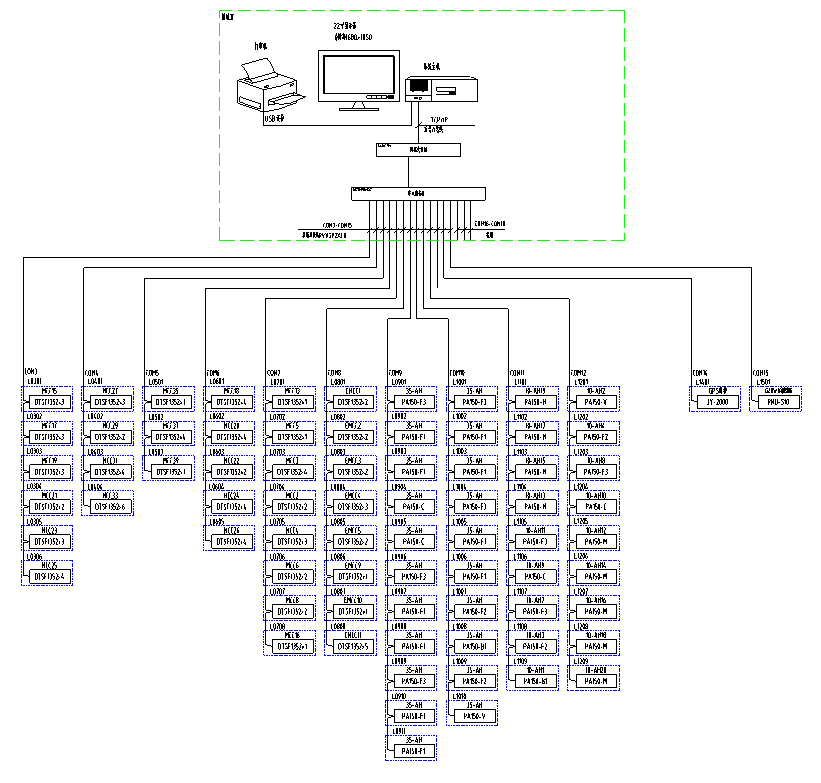
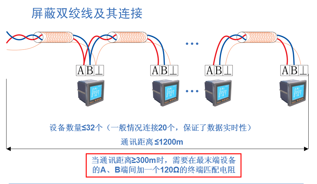
Smart meter on-site connection
The on-site instrument is connected to the serial port server in the data collection box of the corresponding power distribution room through a Shielded Twisted Pair (RVSP2*1.0) in a hand-in-hand manner. The number of smart meters per bus is about 20, and then passes through Suning Plaza in Baotou. The intranet uploads data to the local monitoring terminal. The specific connection diagram is as follows:
3 system function
The real-time monitoring system diagram of the substation is the main monitoring screen. It mainly monitors the running status of all loops of the substation in real time. The red represents the closing and the green represents the opening. In the system diagram, you can intuitively see the operating parameters of the high-voltage cabinet corresponding to the microcomputer protection and the operating parameters and status of the low-voltage part incoming and outgoing lines. You can see all the conventional power parameters of the field intelligent microcomputer protection and power meters, such as: three-phase Voltage, current, active power, reactive power, power factor, frequency, active power, etc. As shown below:

35KV high pressure system diagram
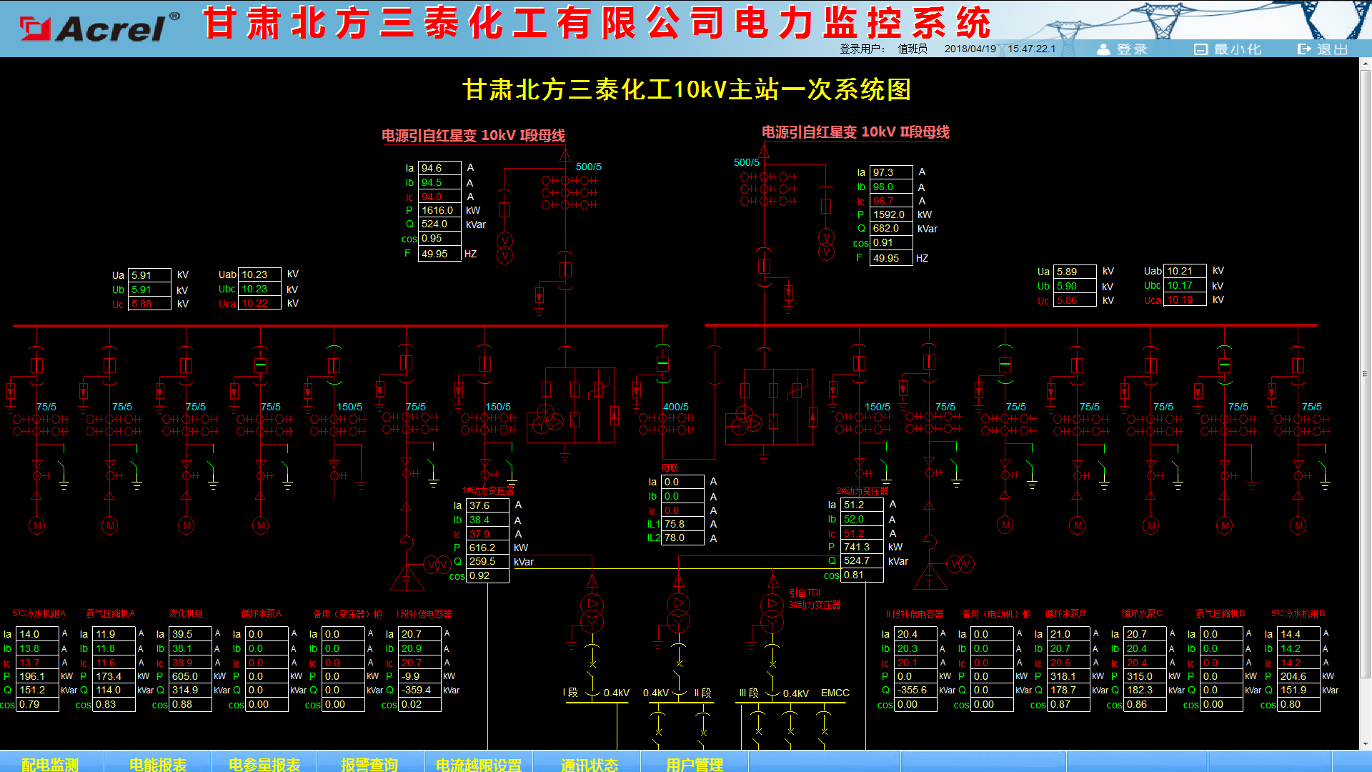
10KV high pressure system diagram
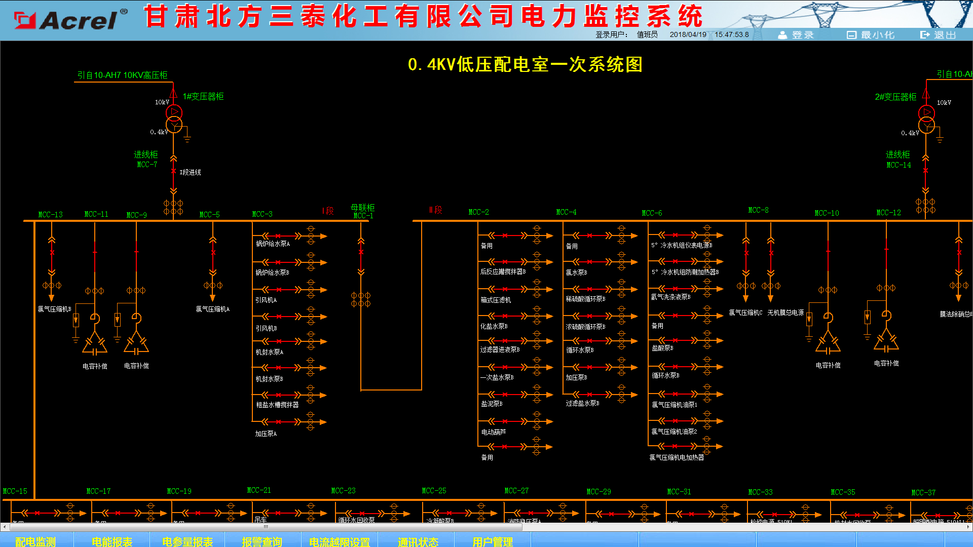
Low-voltage system diagram
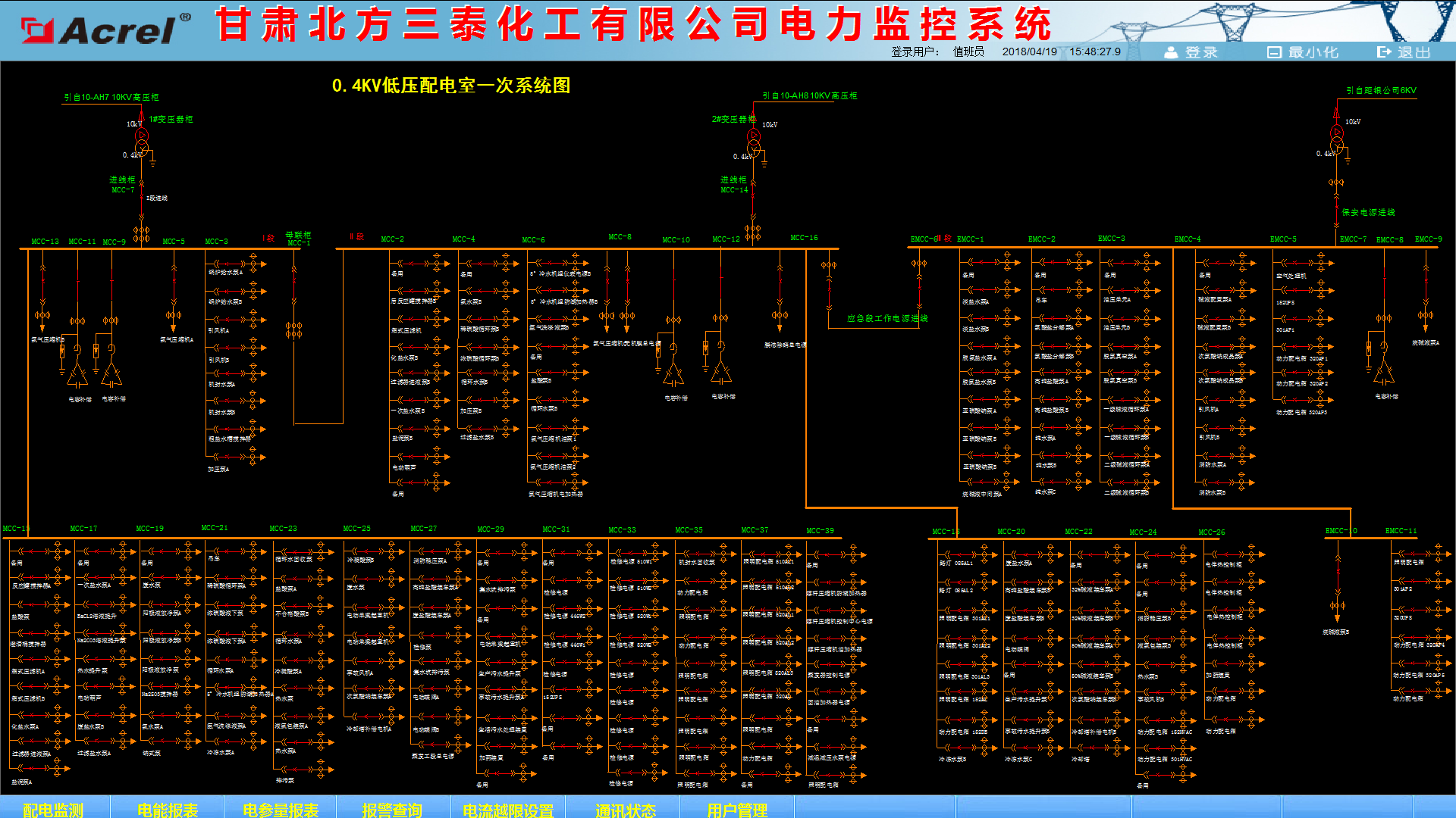
Low-voltage system diagram
The remote signaling and telemetry alarm functions are mainly used to monitor the switching operation status of the high and low voltage loops and the incoming line monitoring of the load. The specific position of the alarm and the audible alarm are indicated for the switch displacement and the load over-limit pop-up alarm interface, prompting the on-duty personnel to deal with it in time. The load limit can be set freely under the corresponding authority. 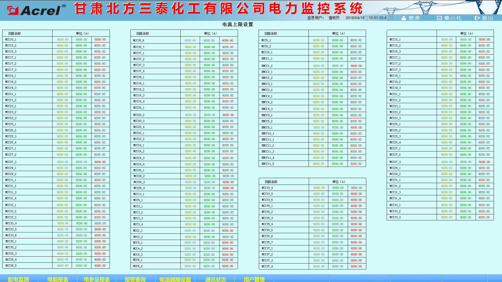
Current limit setting
The event alarm recording function mainly completes the recording of the alarm information events occurring within the query time period and the occurrence time, providing a basis for the on-duty personnel and analyzing the cause of the accident.

Alarm window
The parameter reading function mainly inquires into the electrical parameters of the outlet circuit of high and low voltage. Supports electrical parameter query at any time, with functions such as data export and report printing. This report queries the electrical parameters of different loops corresponding to different processes in the high and low power distribution rooms in the maintenance and upgrading project of Gansu North Santai Chemical Co., Ltd., which mainly includes: three-phase current, active power, and active power. The names of the loops in this report are associated with the database to facilitate the user to modify the loop name. As shown below:
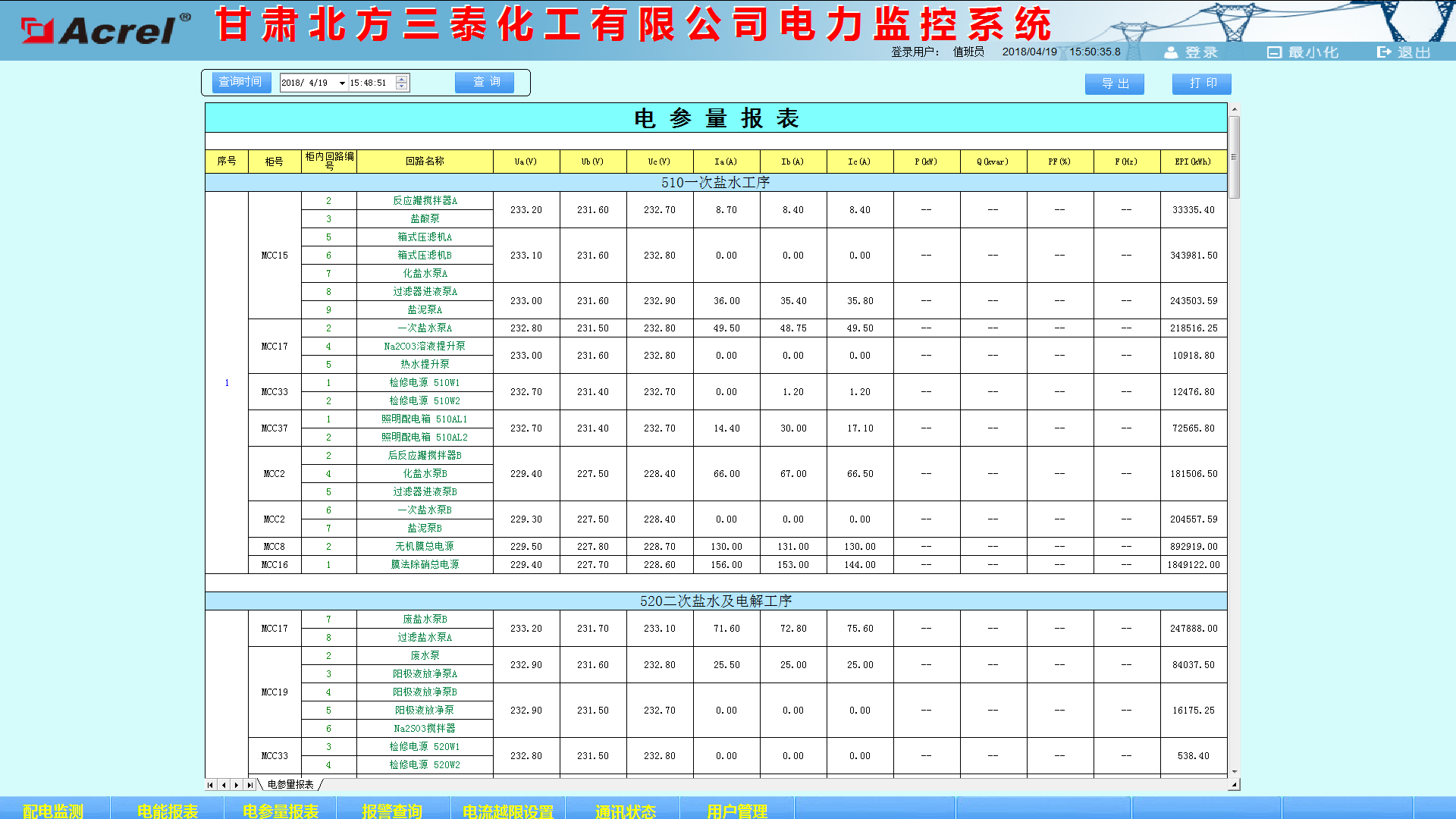
Electrical parameter reading
The electricity consumption report function can select the time period to inquire, support the electric degree cumulative inquiry of the subcircuit, equipment, and operation at any time period, and has the functions of data export and report printing. Provide accurate and reliable power report for duty personnel. The names of the loops in this report are associated with the database to facilitate the user to modify the loop name. As shown in the figure below, the user can directly print the report and save it in EXCEL format to another location. As shown below:
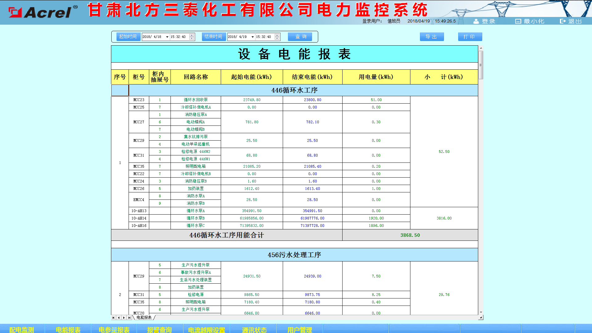
Detailed equipment power report
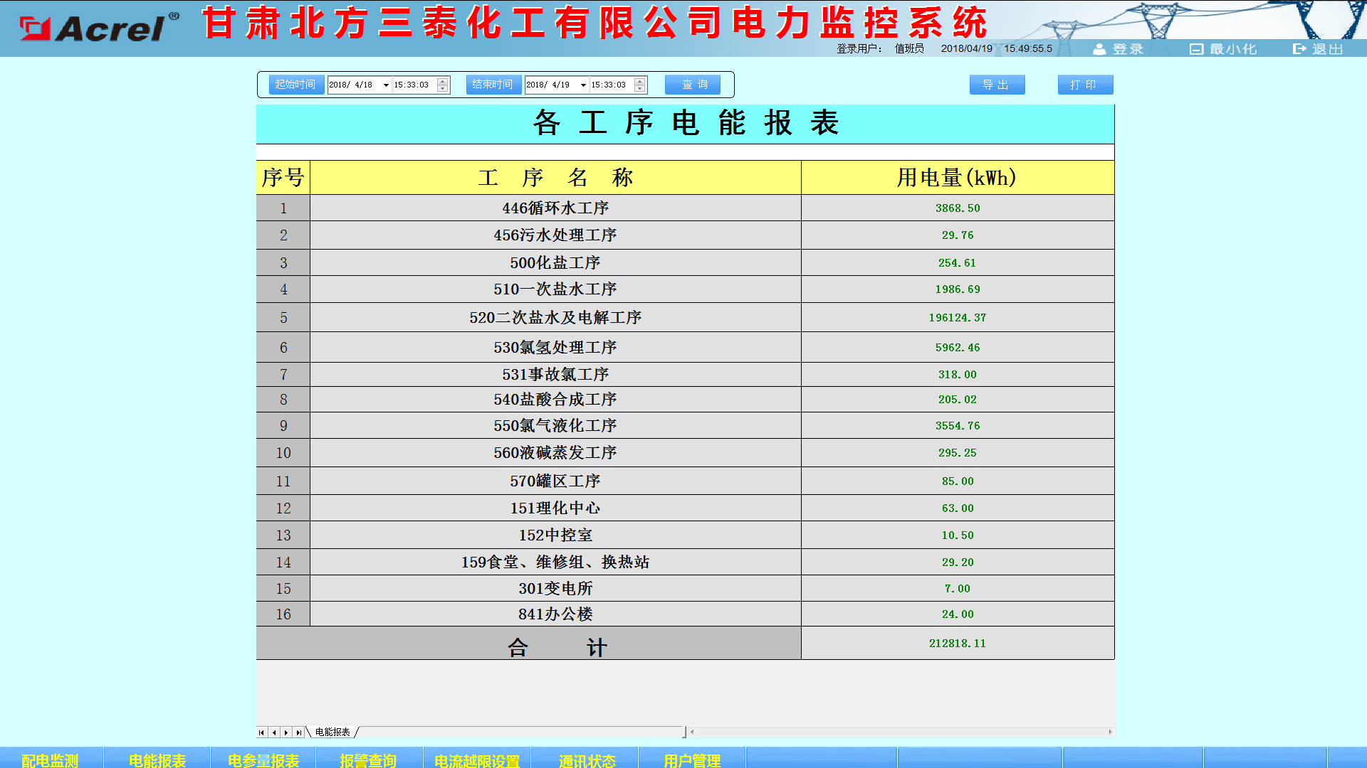
Sub-process energy report
The schematic diagram of the system communication structure mainly shows the networking structure of the system. The system adopts a hierarchical distributed structure and simultaneously monitors the communication status of the equipment at the bay level. Red indicates normal communication and green indicates communication failure. The following figure shows the substation communication status.
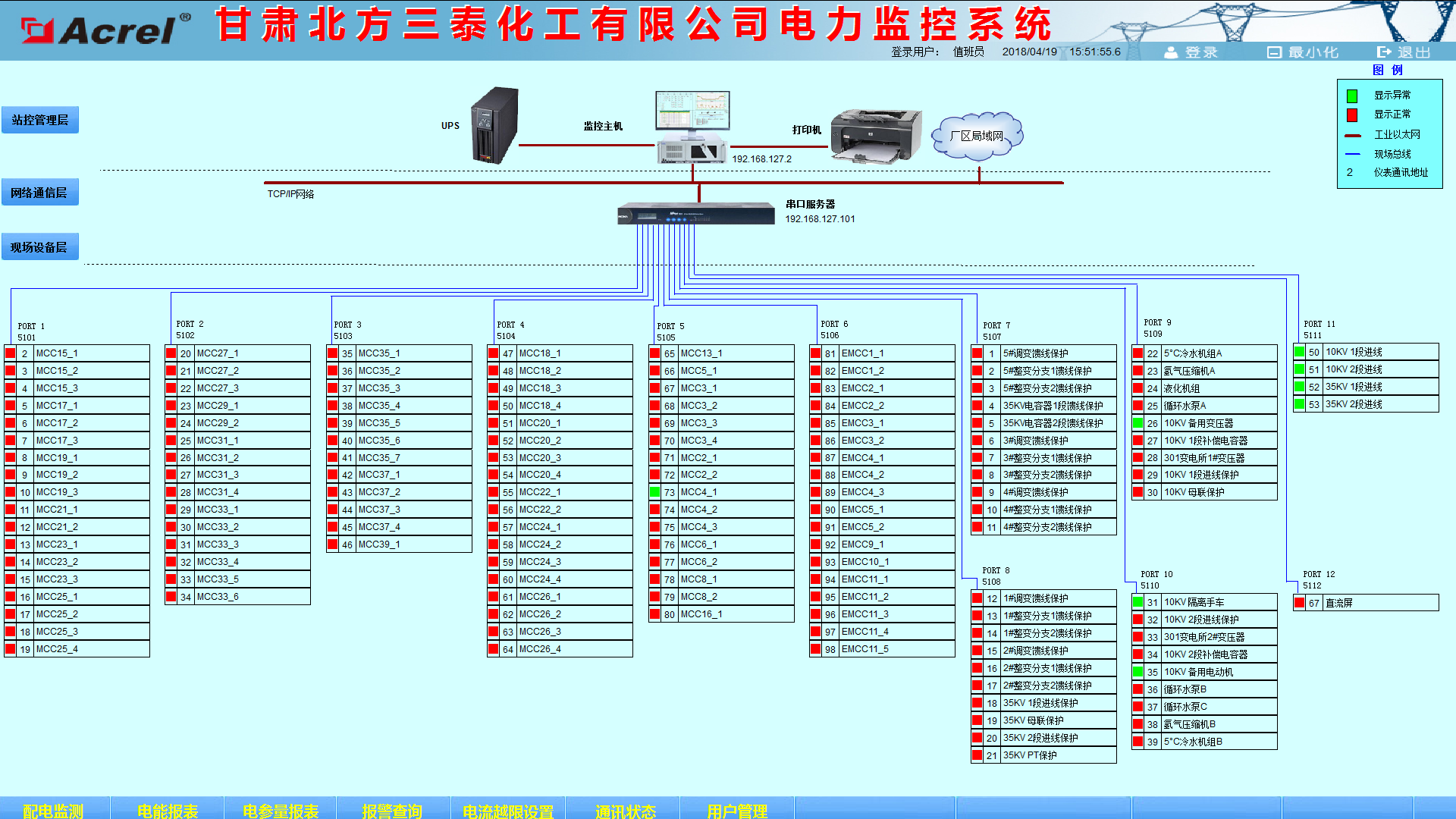
Communication structure diagram
User rights management, assigning different roles to different users, can be assigned to function submenus, specific file records, data records, etc. The following figure shows the permission configuration interface. 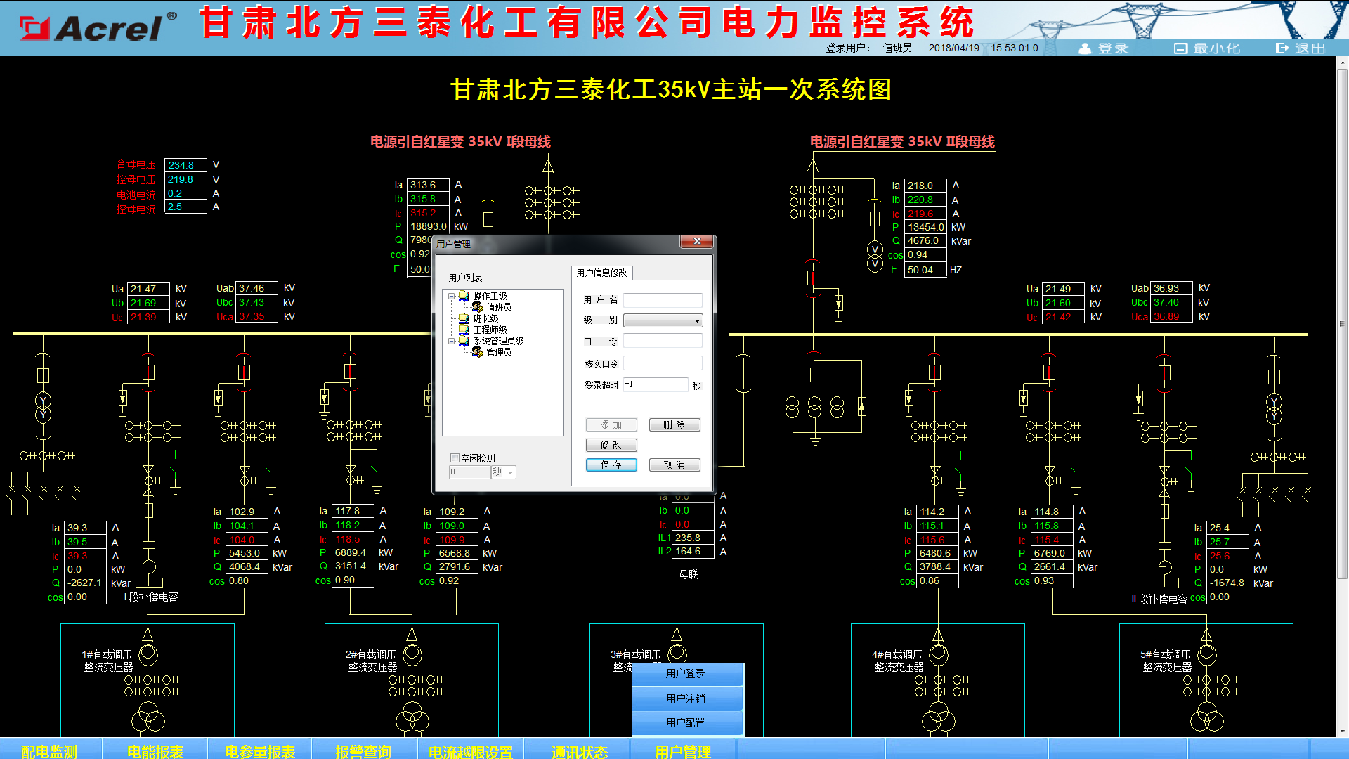
User rights management
4 Conclusion
In the application of power distribution facilities today, the distribution security of large-scale factory projects is of utmost importance. The application of the Acrel-2000 power monitoring system introduced in this article in the maintenance and upgrading project of the Gansu North Santai Chemical Industry Co., Ltd. can achieve Real-time monitoring of the power supply and distribution circuit in the power distribution room. The system analyzes and processes the collected data. It displays the running status of each distribution circuit in the power distribution room in real time. It has pop-up alarm dialogs and voice prompts when the load is exceeded. Various kinds of energy reports are generated to facilitate remote meter reading and analysis and research of electric energy. The system is safe, reliable and stable, providing a real and reliable basis for resolving power problems in the project.
En Flanges,Carbon Welding Neck Flange,Welded Flange,Forged Steel Flanges
Zhangqiu Xinhao Machinery Parts Factory , https://www.xhflange.com