
Lithium-ion batteries have high energy weight and energy-to-volume ratio, no memory effect, many times of re-charging, long service life and lower price. A good charger gives the battery a long life. The intelligent charger designed by C8051F310 single-chip microcomputer has high measurement accuracy, can control the magnitude of charging current, adjust in time, and can judge the charging time according to the state of charging, and terminate charging in time to avoid the battery passing. Charge.
This article discusses the use C8051F310 device lithium ion battery's design. Generating a PWM pulse width modulation using software-controlled charging power supply, charging current required to accommodate the different stages. The temperature sensor monitors the battery temperature and detects the battery charging voltage and current through AD conversion and related calculations to determine which stage the battery reaches. Make the battery have a longer life and a more efficient charging method.
designing process
1 charging principle
The characteristics of the battery uniquely determine its safety performance and efficiency of charging. The best way to charge a battery is determined by the chemical composition of the battery (lithium, nickel, nickel, or SLA ). Still, most charging solutions include the following three phases:
â— Low current regulation stage
â— Constant current stage
â— Constant voltage stage / charge termination
All batteries are charged by transferring energy to themselves. The maximum charging current of one battery depends on the rated capacity of the battery ( C ). For example, a battery with a capacity of 1000mAh can charge 1C when the charging current is 1000mA . (1 times the battery capacity) can also be used 1 / 50C (20mA) or less current to charge the battery. However, this is just a normal low current charging method and is not suitable for fast charging solutions that require short charging times.
Most chargers in use now charge both the low current charging method and the rated charging current, that is, volume charging, which is usually used in the initial stage of charging. At this stage, the initial self-heating effect of the chip, which will cause the termination of the charging process, is minimized. Volume charging is usually used in the intermediate stage of charging, and most of the energy of the battery is stored at this stage. In the final stage of battery charging, most of the charging time is usually consumed at this stage, and the value of current, voltage or both can be monitored to determine when to end charging. Similarly, the end scheme relies on the chemistry of the battery. For example, most lithium-ion battery chargers keep the battery voltage at a constant value while detecting the lowest current. Nickel-cadmium and NiCd batteries use a rate of change in voltage or temperature to determine the end time of charging.

Some of the electrical energy is converted to heat during charging until the battery is fully charged. When fully charged, all of the electrical energy will be converted into heat. If the charging is not terminated at this time, the battery will be damaged or burned. Fast charger batteries (chargers that are fully charged for less than two hours) can solve this problem because they use high charging currents to reduce charging time. Therefore, for a lithium-ion battery , monitoring its temperature is critical because the battery will burst when overcharged, and temperature changes should be monitored at all times during the charging phase, and at temperatures above the maximum set point. Stop charging immediately.
2 overall design
The charging circuit consists of three parts: a control part, a detection part and a charging part. As shown in Figure 1 , the F310 MCU is used for charging control. The MCU itself has all the functions required for pulse width modulation PWM type switching regulator power supply, and has a 10 -bit A/D converter. The battery voltage, current, and temperature detection circuit are constructed by using the A/D port of the single chip microcomputer .
Through the voltage feedback and current feedback signal, the single-chip microcomputer directly converts the digital voltage signal into an analog voltage signal by using the PWM output, which can ensure the control precision.
3 control part of the circuit design
C8051F310 microcontroller
1 analog peripheral
a. 10 -bit ADC : conversion speed up to 200ks/s, up to 21 or 17 external single-ended or differential inputs, VREF can be selected on external pins or VDD , built-in temperature sensor (± 3 °C), external conversion Start input
two analog comparators b: programmable hysteresis and response time, can be configured to interrupt or reset source, low current (<0.5 μ A).
2 supply voltage
a. Typical operating current: 5mA , 25MHz ;
. b Typical shutdown current: 0.1 μ A;
c. Temperature range: -40 to +85 °C.
3 high speed 8051 microcontroller core
a. Pipeline instruction structure: 70% of the instructions are executed for one or two system clock cycles;
b. The speed can reach 25MI/s (when the clock frequency is 25MHz );
c. Extended interrupt system.
4 digital peripherals
A.29/25 port I/O : all port lines are resistant to 5V ;
b. 4 general purpose 16 -bit counters / timers;
c. 16 -bit programmable counter / timer array ( PCA ) with 5 capture / compare modules;
d. Real-time clock mode using PCA or timer and external clock source.
In the control circuit, as shown in Figure 2 , the P0.3 port provides charging power, the P0.6 port detects the charging voltage, the P0.5 port detects the charging current, and the P0.4 port detects the battery temperature.
The charging current is generated by the PWM pulse width modulation PWM , and the charging current is calculated by AD conversion. Â
4 charging part and detection part circuit design
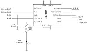
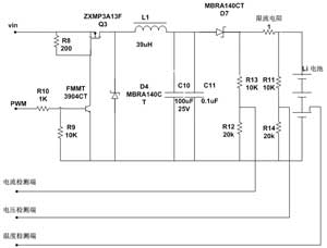
Figure 3 is a diagram of a charging circuit and a detecting circuit.
1 charging process curve
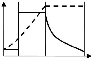
As shown in FIG. 4 , the charging process consists of a precharge state, a constant current state of charge, and a constant voltage state of charge.
2 fast converter
The most economical way to achieve a fading termination of the charger is to use a fast converter. A fast converter is a switching regulator feedback circuit that uses an inductor and / or a transformer (which requires a transformer when isolated) as an energy storage unit to transfer energy from the input to the output in discrete energy packets. The energy is regulated by the transistor. The transmission is also used as a filter switch to ensure that the voltage or current remains constant during the load.
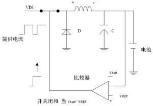

a switch closed       b switch open
The operation of the fast regulator is achieved by controlling the duty cycle of a transistor switch. The duty cycle is automatically increased to allow the battery to flow more current. When VBATT
3 inductance determination
Inductance is hampering AC power. Under certain circumstances the frequency of the alternating current, the greater the inductance, the stronger the blocking capacity of the AC ?? certain circumstances, the higher the frequency of alternating current, the greater the inductance of the alternating current blocking capacity, the lower the frequency, the inductance of the alternating current The smaller the obstacle ability. That is to say, the inductance has the characteristic of preventing the passage of the alternating current.
The working principle is as follows: When the voltage across the load is to be reduced , the external power supply charges the inductor and reaches the required voltage rating through the switching action of the MOSFET field effect transistor. When the voltage across the load rises , the external power supply is disconnected by the switching action of the MOSFET field effect transistor, and the inductor releases the energy just charged, and the inductor becomes the power supply to continue to supply power to the load. The energy stored on the inductor is consumed. The voltage across the load begins to gradually decrease, and the external power supply is charged again by the switching action of the MOSFET FET. In turn, a stable voltage is formed during constant charging and discharging, and the voltage across the load will never rise or fall, which is the biggest advantage of the switching power supply.
To determine the size of the inductor in the fast converter, first assume that the duty cycle of the transistor is 50% , because converter operation is most efficient at this time. The duty cycle is given by Equation 1 :
(where T is the period of the PWM in the program example T = 10.5s )
Duty cycle = ton / T Â Â Â Â Â Â Â Â Â Â Â ( 1 )
At this point, you can select a PWM conversion frequency (as shown in Equation 2 ) . The larger the conversion frequency of the PWM , the smaller the value of the inductor and the more cost-effective.
My example code configures the F310 's 8 -bit hardware PWM to use a 256 division of the internal 24.5MHz master clock to produce a 95.7kHz conversion rate.
L= ( Vi-Vsat-Voton ) /2Iomax   ( 2 )
Now we can calculate the size of the inductor. Assuming that the value of the charging voltage Vi is 15V , the value of the saturation voltage Vsat is 0.5V , the output voltage value to be obtained is 4.2V, and the maximum output current I O MAX is 1500mA . The value should be chosen at least 18H .
It should be noted that the capacitor in this circuit is only a ripple attenuator. Because the ripple is inversely proportional to the size of the capacitor, the larger the value of the capacitor, the better the attenuation effect.
It can be used for mineral oils, lubrication oils, non-flam fluids, synthetic and rapidly biodegradable fluids filtration.
Pressure oil filter houing, hydraulic oil filter
Xinxiang Shengda Filtration Technique Co., Ltd. , https://www.shengdafiltration.com