
Regardless of the name, new capacitors such as ultracapacitors or supercapacitors are much larger than those of conventional capacitors . Directly speaking, you can now purchase a radial leaded on-board capacitor with a rating of 5~10F/2.5V, a flash-cell capacitor with a rating of 120~150F/5V, and a larger single capacitor can reach 650. ~3000F/2.7V capacitance value. Note that the capacitance values ​​of all these capacitors are in Farads. Not too long ago, two thousand microfarads were considered large capacitors.
If you need more types of capacitors, you can order a variety of capacitors with capacitor ratings from 20F to 500F and voltage ratings from 15V to 390V. If you use the appropriate serial/parallel combination, you can even drive a bus with this type of capacitor—yes, not the wiring on the board, but the passenger bus. (Although hybrid fuel systems, chemical batteries and fuel cells are just around the corner, they have not been officially put into use).
When developing ultracapacitors, people did not find any new laws of physics. In fact, the principle of supercapacitance still goes back to the German physicist Helmholtz. Like ordinary capacitors, supercapacitors store energy in the form of stored charges between two "plates." The magnitude of the capacitance is proportional to the area of ​​the plates and the dielectric material used between the plates, and inversely proportional to the distance between the plates. However, the principle of supercapacitors is different.
Before we realized the huge capacitance with supercapacitors, we have mastered the principle of electrochemistry. Ultracapacitors are not electrolytic chemistry, but understanding electrochemistry helps us understand the new technology of supercapacitors.
It is called electrolytic chemistry because one (or two) of its "plates" are non-metal electrolytes formed on the surface of a metal substrate. During the manufacturing process, a voltage drive current flows from the anode metal plate through the conductive plating bath to the cathode. This creates an insulating metal oxide-dielectric on the surface of the anode.
In electrolytic chemistry, when the electrode is immersed in the electrolytic solution, charge accumulation and charge separation occur at the electrode interface. The accumulation of reversely charged ions in the electrolyte compensates for the residual charge on the electrode surface. This interface is called the Helmholtz layer.
The structure of the ultracapacitor is no longer the structure of a flat electrode (or a flattened flat electrode) that is filled with a dielectric material - like a peanut butter in the middle of a sandwich. In the supercapacitor, charge/discharge of charges occurs at the interface between the porous carbonaceous material or the porous metal oxide in the electrolyte.
The Helmholtz layer causes an effect called a double layer capacitor. When a DC voltage is applied to both ends of the porous carbon electrode in the supercapacitor, the cation or anion for charge compensation accumulates in the electrolyte around the charged electrode. If electron migration does not occur at the interface, the "two-layer" separated charge (electrons or electron holes on the metal side, and the cation or anion on the electrolyte side of the interface boundary) will appear on the interface (see figure 1)).
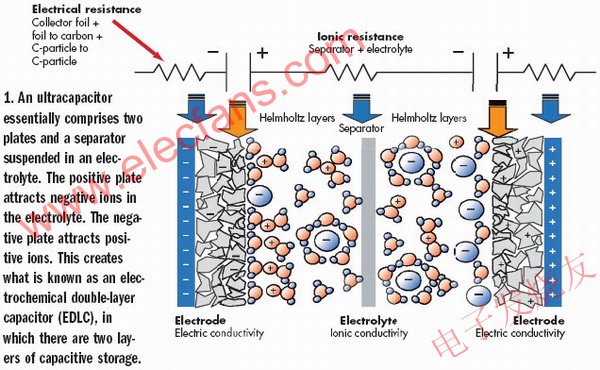
Figure 1: The supercapacitor essentially consists of two plates and a separator suspended in an electrolyte. The positive electrode plate attracts anions in the electrolyte. The negative plate attracts cations. This forms a so-called electrochemical double layer capacitor (EDLC) with a two-layer capacitive storage structure.
The size of the Helmholtz-region capacitor depends on the area of ​​the porous carbon electrode and the ion capacity in the electrolyte. The capacitance per square centimeter on the double layer electrode is 10,000 times that of the ordinary dielectric capacitor. This is because the distance between the charges in the two-layer electrode is only about 0.3 to 0.5 nm, while in electrolytic chemistry this distance is 10 to 100 nm, and the mica or polystyrene capacitance is 1000 nm.
We have already understood the principle of this "double layer" electrode. However, this two-layer structure reduces the theoretical capacitance that the actual device should achieve because the supercapacitor includes a pair of electrodes, each of which has an area of ​​only half of the total area. In addition, the supercapacitor is actually a series of two capacitors connected in series. Therefore, the actual capacitance of the supercapacitor is only a quarter of the theoretical capacitance calculated from the electrode area and ion capacity.
Battery and super capacitor
Some literatures like to confuse batteries with supercapacitors, masking many important differences between the two:
The battery stores the energy calculated in watt-hours, and the capacitance stores the power in watts.
The battery provides electrical energy with a constant chemical reaction for a long period of time, and the charging time is relatively long, and the characteristics of the charging current are demanding. Instead, the charging of the capacitor is done by loading the voltage across it, and the charging speed is largely dependent on the external resistance. The battery is capable of outputting electrical energy at a substantially constant voltage for a longer period of time. The discharge speed of the capacitor is fast, and the output voltage is exponentially attenuated.
The battery can only maintain a good working condition within a limited number of charge/discharge cycles, and the number of charge/discharge cycles depends on the degree of discharge. Capacitors, especially supercapacitors, can be charged/discharged tens of millions of times. (This is also an important aspect of supercapacitance different from electrolytic chemistry - they do not have the limit of the number of charge and discharge times of the electrode plates as in the electrolysis process.)
The battery is cumbersome and the capacitor is lighter.
Many differences between batteries and capacitors can be visualized using the Ragone diagram (see Figure 2). Ragone plots are often used for analysis, but in reality, the Ragone plot is a double logarithm between the energy density (in Wh/kg) on ​​the Y-axis and the power density (in W/kg) on ​​the X-axis (log -log) Diagram. Since it is a double logarithmic graph, the discharge time can be expressed as a line diagonal parameter.
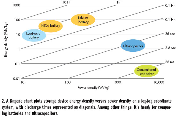
Figure 2: The Ragone diagram represents the log-log relationship between the energy density of the energy storage device and the power density, where the discharge time is represented as an oblique diagonal. This figure is also very convenient to compare the characteristics of the battery and the super capacitor.
The Ragone diagram in Figure 2 shows the difference between different kinds of chemical cells (collected on the left side of the figure) and different kinds of capacitances (on the right side of the figure). According to the Ragone diagram, these characteristics make the battery and the supercapacitor form a complementary rather than a contradictory relationship. In fact, this is why they are universally applied.
Latest application
The primary application of ultracapacitors is to stabilize the DC bus voltage. Supercapacitors have been widely used in the automotive industry to protect various engine control components and microcontrollers from voltage sags caused by sudden changes in transient loads. (The voltage spike is handled by Other methods.)
These transient load changes are usually associated with the engine. However, if the speaker output power of the car entertainment system is relatively strong, then this load may also originate from the audio pulse peak. Unlike simply placing a supercapacitor on the 12V voltage input of an in-vehicle entertainment system, an application note from Australian supercapacitor manufacturer Cap-XX gives a way to increase the H-bridge voltage of a Class D output amplifier ( As shown in Figure 3). A small boost converter is used to store the power required for accidental peaks in a pair of supercapacitors.
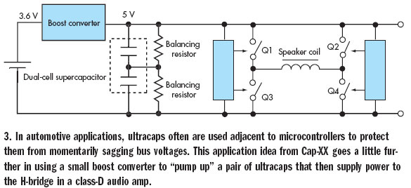
Figure 3: In automotive electronics applications, supercapacitors are often used in conjunction with microcontrollers to protect them from bus voltage dips. The application example in the figure further uses a small boost converter to "boost" the two supercapacitors, which then power the H-bridge in the Class D audio amplifier.
In addition, in the field of transportation, ultracapacitors have the ability to quickly absorb and release energy, and are more suitable for regenerative braking mechanisms than batteries. Most of these uses have already been applied in the public transport industry (see Figure 4). The Bombardier tram in the light rail system of Mannheim, Germany, uses 600 2600F ultracapacitor sets to achieve the braking energy recovery mechanism. The stored energy is used for the acceleration of the vehicle and the power connection of the unpowered road sections and intersections. This is an all-electrical rail system that reduces the amount of braking energy required to reduce the required transmission network. From this point of view, the prototype system proved to achieve 30% energy saving effect.
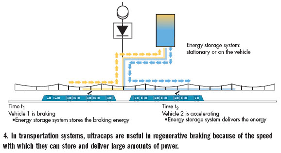
Figure 4: In a transportation system, supercapacitance is very useful for regenerative braking technology because it stores the energy of the vehicle's braking and releases a lot of energy when needed.
Mannheim installed the supercapacitor on the body of the tram, and the other way is to mount the supercapacitor on both sides of the track. In demonstrating this implementation, Siemens Transportation Systems used supercapacitors in its Sitras SES system to implement a braking energy recovery unit for metro lines in Cologne and Madrid. In a typical trackside implementation, the supercapacitor is capable of absorbing braking energy for all trains within a radius of 3 km.
In hybrid transportation applications in the United States, buses running ISE in Elk Grove and Long Beach have faster acceleration than regular buses. In the case of gross vehicle weight, the bus is capable of achieving 0 to 31 mph acceleration in less than 17 seconds and can reach a maximum speed of 62 mph. Relevant statistics show that systems based on ultracapacitors have higher average fuel efficiency than battery-based hybrid electric systems. Hybrid buses that use this ultracapacitor plus battery design can recover 38% of the propulsion energy, which is equivalent to an average fuel efficiency increase of 3.9 mpg.
ISE has developed its own thermal control module, each module uses 144 18F ultracapacitors. This module is capable of delivering 360V at 400A. A pair of such modules connected in series to achieve a rated voltage of 720V (800V peak voltage). This two-component structure supports charge and discharge cycles up to 300 kW power levels and is capable of storing approximately 0.6 kWh of energy.
Regenerative braking technology recovers kinetic energy. Such applications are also capable of recovering potential energy. A recent example is the application on forklifts, but the broader potential application market is the construction elevator system.
In the field of forklift applications, General Hydrogen has introduced a new "Hydricity Packs" fuel cell system that is sized to directly replace lead batteries in traditional industrial equipment. The ultracapacitor group can store potential energy every time the loading and unloading fork carrier tray descends, and release energy when the weight is raised to increase power. Figure 5 shows a typical forklift power usage profile that illustrates the synergy between the fuel cell and the supercapacitor.
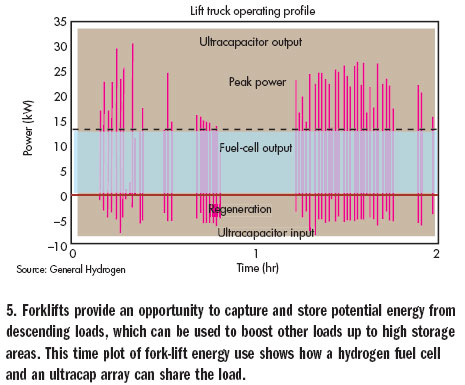
Figure 5: The forklift can capture and store the corresponding potential energy when lowering the cargo, which can be used to lift other cargo to a higher inventory area. The time diagram of the forklift energy indicates the case where the hydrogen fuel cell and the supercapacitor array share the load.
Short discharge times have a positive effect on certain supercapacitor applications. In European wind farms, the latest wind turbine blades have a diameter of 160 ft and the axle is 250 ft above the ground. When the wind is large, the blade rotates faster to prevent the turbine from rotating in the opposite direction. This requires a high torque adjustment motor and corresponding power supply for each blade.
Although such systems can be implemented with lead batteries, ultracapacitors are used in the design of wind turbines. The battery may require regular maintenance, while the supercapacitor does not. Of course, the maintenance of the battery requires the employment of some skilled service personnel to climb the tower. They must focus on heavy maintenance and climb up and down on thousands of towers to effectively maintain the battery.
Circuit design
The combination of ultracapacitors, batteries, fuel cells and solar panels has produced many novel designs. A number of such programs are presented in a recent paper presented at the Power Electronics Conference in Dallas, representing the current state of the art in this technology.
In a paper titled "Storing Power with Super Capacitors," Thomas DeLurio of Advanced Analogic Technologies, Inc. pointed out that some portable applications, such as GSM, GPRS, or WiMAX communications, use wireless data cards in the transmission of data signals. Peak current support is required, and this peak current is beyond the scope of PC cards, CF cards or USB standards.
DeLurio also found similar problems with LED flash lighting devices for cell phone cameras. He said, “The challenge for designers is how to interconnect the battery, DC-DC converter and supercapacitor in the most efficient way, limiting the charging current of the supercapacitor and re-energizing the capacitor between load events. Charging."
DeLurio believes that the problem with ultracapacitors is that their ESR (equivalent series resistance) is low. When the initial capacitor is discharged, it acts like a low value resistor for the charging circuit. The resulting transient high current actually causes a short circuit in the battery. In addition, he pointed out that "all this type of circuit requires short circuit, overvoltage and current protection mechanisms."
Designers can use resistors in series to limit the current, but this approach can cause the capacitor to charge for too long and unacceptable. DeLurio introduces a PC card application in which the resistance set to limit the PC card host/card communication current is such that the charging time is on the order of 7 minutes.
Using a larger current after host/card communication can shorten the charging time. In fact, if this principle is further extended, the capacitor can be switched in a certain way during the charging process to achieve the purpose of controlling the current.
But this method "requires precise control of the timing of the switching point, which may require very precise and expensive resistors, or an additional voltage detector for monitoring," DeLurio said. "And, when the capacitor is fully charged and When the PC card is unplugged, the energy stored in the capacitor is enough to damage the pins."
Instead, DeLurio introduced a new "smart switch" from Analogic Tech. The AAT4620 current-limited P-channel MOSFET power switch is specifically designed for wireless card supercapacitor applications. It has two independent, resistor-programmable current limit circuits and a power loop controlled by the AAT4620 core temperature.
The article "Super-Capacitor Power Storage" by Keith Curtis of Microchip first pointed out that charging a supercapacitor with a linear charger is ineffective. He then introduced an improved DC-DC buck regulator (shown in Figure 6a) as a suitable charging circuit because this circuit can "adjust the charging current of the capacitor, independent of the output voltage... using voltage feedback As a basis for judging whether or not charging is completed."
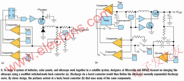
Figure 6: In order to integrate batteries, solar panels and ultracapacitors in a satellite system, Microchip and AMSAT designers used an improved switching buck converter to charge the supercapacitor (a). The discharge through the boost converter will flatten the normal exponential discharge curve of the supercapacitor, and the combination of the buck/boost converter (b) uses many of the same components.
The effect of this circuit is similar to that described by DeLurio, but it is more versatile. For the way the circuit works, "current... is regulated by comparing the current in the inductor with two fixed current values; one is the expected maximum current and the other is the minimum current," Curtis said.
“Initially, the inductor can rise from the minimum current to the maximum current in a short time because the voltage across the inductor is at its maximum. The discharge time will be extended accordingly because the inductor must discharge to a relatively low voltage value. "But, as the charge inside the capacitor increases, the voltage difference will drop - increasing the rise time - the capacitor voltage will rise and shorten the discharge time."
Curtis pointed out that the switching frequency depends on "a relaxation oscillator with two comparators and an SR flip-flop, a 555-timer-style system", so the component value of the inductor determines the magnitude of the frequency.
Curtis then uses a similar logic to implement a switching boost circuit that converts the output voltage of the capacitor to a reasonable constant load voltage. In the end, Curtis implemented a buck/boost charge-discharge combination circuit in which a switching MOSFET was used instead of a flyback diode in the charging circuit (as shown in Figure 6b), using a PIC microcontroller for control functions. And most of the required peripheral functions.
Microchip has partnered with AMSAT-NA, a non-profit private organization that targets amateur radio satellite research and development. AMSAT's next large project, the Eagle Satellite, is scheduled to launch in March 2009. In order to ensure that Eagle can work continuously for decades, its power system will be based on this work, integrating solar panels, lithium-ion batteries and ultra-capacitors into a power system to optimize the use of each component.
Pipe Fitting,Stainless Steel Threaded Pipe Fittings,Threaded Pipe Fittings
East Well Valve Co., Ltd. , http://www.shballvalve.com