
introduction
The thermal vacuum test chamber is an environmental simulation test equipment that simulates the space environment on the ground. In recent years, thermal vacuum test equipment has played an important role in the development and finalization of products in the aerospace industry. Due to the complex structure of the thermal vacuum test chamber, some abnormal phenomena may occur during operation. If it cannot be eliminated in time, the test period will be prolonged and the product development work will be affected. For this purpose, we briefly explain the basic working principle of the test chamber, and introduce how to analyze and judge the general failure of the thermal vacuum test chamber.
1 Working principle of thermal vacuum test box
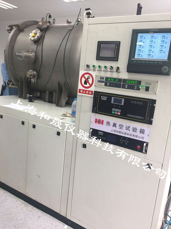
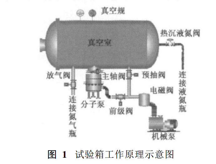
The following describes the working process of the HS-2P-ZQ thermal vacuum simulation device as an example. The test chamber consists of a main pump turbo molecular pump, a mechanical pump, a pre-pump valve, and a main pumping valve to form a vacuum unit. The vacuum chamber is evacuated to obtain a relatively clean high vacuum test environment. The box heat sink is heated or cooled by heating wire or liquid nitrogen, and a relatively uniform temperature field is formed in the heat sink of the box by means of radiation conduction, thereby obtaining an existing vacuum and a wide range of temperature -100°C~ 125°C space simulation environment. After the hot vacuum test was completed, open the purge valve and fill it with nitrogen to remove the test piece. The working principle of the test box is shown in Figure 1.
2 Failure Analysis
Because the test box is a more complex electromechanical assembly system, once the equipment is abnormal, the entire equipment must be inspected and comprehensively analyzed in a comprehensive and orderly manner. For the occurrence of a fault phenomenon, the principle of first outside and inside is firstly performed. That is, external factors such as cooling water and power supply are eliminated first. After the external factors are completely eliminated, an electromechanical correlation method is used to find the cause of the fault according to the fault phenomenon. In accordance with the electrical schematics to find the electrical system and computer software problems, and finally check
The problem of finding a mechanical system is shown in Table 1.
3 Analysis and Diagnosis of Typical Faults
3. 1 failure phenomenon
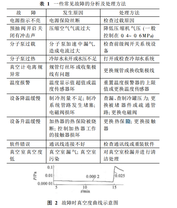
For example, when a specimen is subjected to a thermal vacuum test, it is required that the temperature drop to -55 °C at a vacuum of 2.X10-3 Pa and keep warm for 2 hours. Under normal circumstances, the vacuum degree at this time will be better than 2X10⁻³Pa, but After cooling down for 5 minutes, there was a sudden drop in vacuum to 2.5X10⁻²Pa, as shown in Figure 2. For this purpose, we will carry out the investigation according to Table 1.
3.2 Analysis and Diagnosis of Failures
(1) Disconnect the cooling control, close the refrigeration valve, check for looseness of the vacuum gauge's communication interface, and check whether the speed of the molecular pump has changed. The check is normal, indicating that the vacuum unit problem can be eliminated.
(2) Due to the abnormal vacuum curve during the low temperature cooling period, first observe whether the high vacuum curve can reach the high vacuum requirement under normal temperature and high temperature conditions. The curve shows that the vacuum degree can reach 2X10⁻³Pa or more, and it works normally, indicating that the main power supply is The electrical circuit to each solenoid valve is normal and there is no problem with the electrical system.
(3) Although there is no problem with the electrical system, when the liquid nitrogen is introduced under 2X10⁻³Pa vacuum, this failure indicates that the failure should occur in the chamber refrigeration section. First, tighten the screws on the pumping ports of the box. Fill the nitrogen nitrogen at a pressure of about 0.5 kg at the inlet of the liquid nitrogen. Observe that there is a slight change in the displayed value of the high vacuum gauge.
(4) Combine the control process of the test chamber to further confirm the cause of the failure. Because the heat sink of this equipment uses a 1.5mm thick copper plate as the cavity material, the internal liquid nitrogen coil is made of a long copper tube. Due to thermal expansion and contraction, there is no weld in the vacuum chamber. Heat leakage may occur at the external connection of the heat sink. At this point, it can be considered that the cause of this failure is the occurrence of air leakage at the connection of the solenoid valve and the metal bellows connection vacuum chamber.
(5) The metal bellows connected to the vacuum chamber was disassembled and the solenoid valve was found to be cracked due to prolonged high and low temperature tests. The stem of this solenoid valve was re-welded to heat the test box in a vacuum environment. The liquid nitrogen was filled and the vacuum degree reached 2X10⁻³Pa or more. The test box was working properly.
1. The inner core of the electric heat pipe is made of high-quality stainless steel or other materials, with a coat of PTFE, which is highly corrosion-resistant and suitable for heating various corrosive liquids.
2. Low surface power design (1.5kw /CM) to ensure the service life of the product.
3. The installation position of the electric heater should be paid attention to prevent the solid in the solution from depositing on the surface of the electric heater, or the liquid is too thick and the liquid level is too low, which will cause the teflon tube (PTFE) to be burnt due to the poor surface heat.
4. The shape is divided into vertical type and bottom heating "L" and "Z" type.
Teflon Electric​ Heater,PTFE Electric​ Heater,Teflon Ptfe Immersion Heater Element
Guangzhou Quanxu Technology Co Ltd , https://www.skysilmattingagent.com